Alternating-Current Circuits

Alternating-Current Circuits
The purpose of this is to give quick reference to information or to use in an emergency (like if your text has accidentally been left under your desk at school).
This is NOT intended to replace reading the text with its excellent photographs, diagrams, charts, and tables.
ALTERNATING CURRENT
In 1895, Guglielmo Marconi developed the first practical wirelss telegraph system.
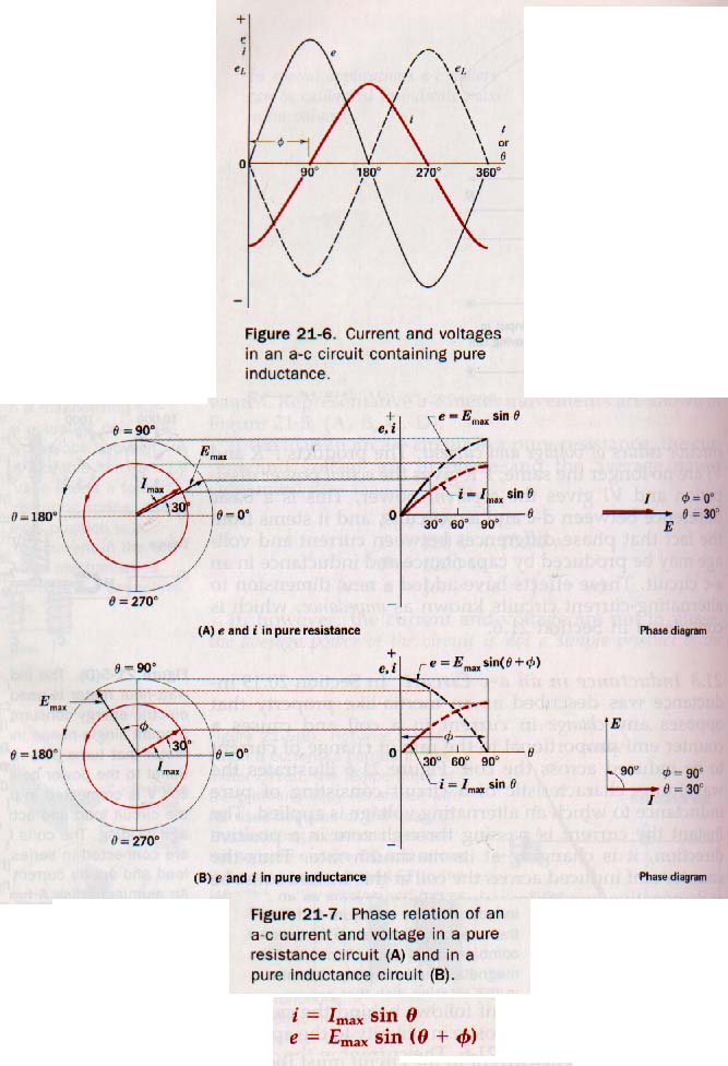
Instantaneous values for voltage
e = Emaxsinq
Instantaneous value for current
i = Imaxsinq
AC Power
P = ei

Effective Values of Current and Voltage:
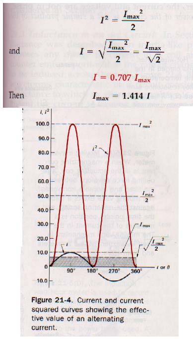
RMS (root mean square) values of AC:

Inductance in AC Circuits:
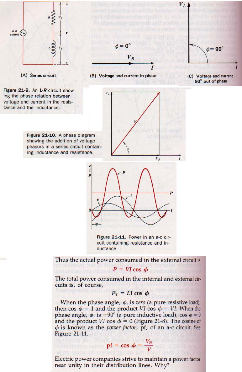
Inductance and Resistance:
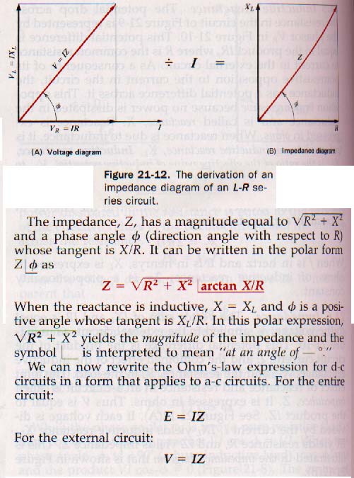
Inductive Reactance and Impedance:
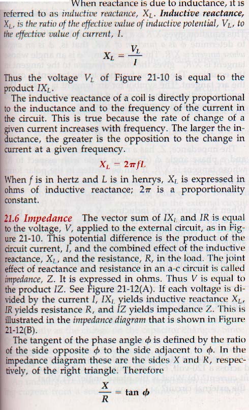
So, it's:
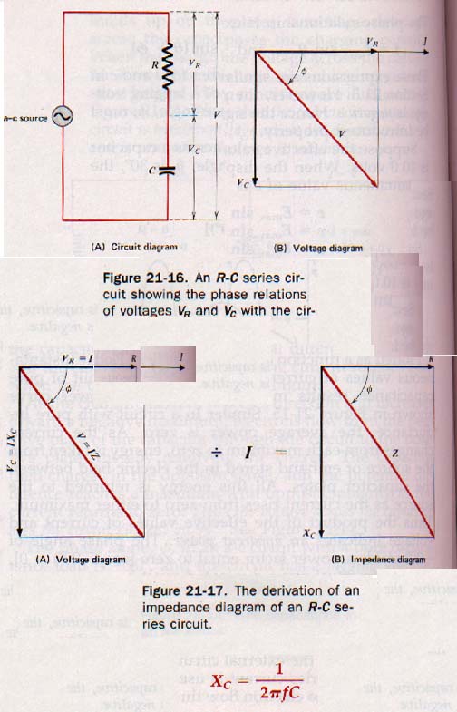
Capacitance in an AC Circuit:

Capacitance and Resistance:
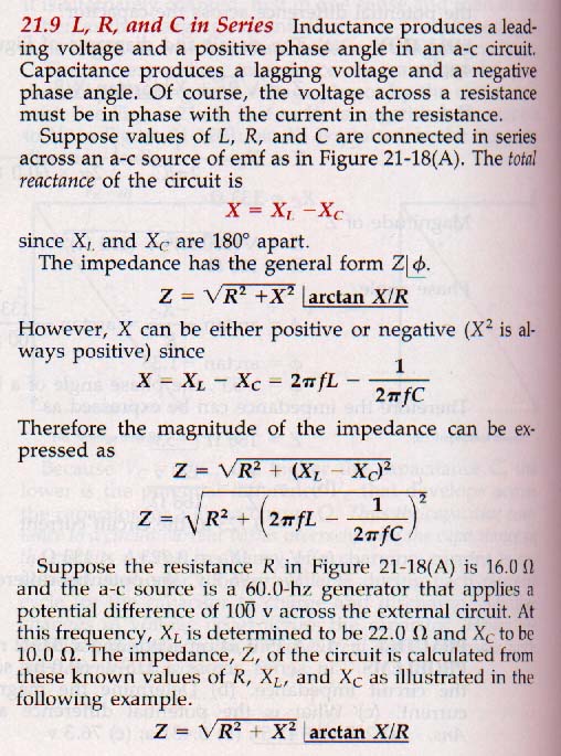
L, R, and C in Series:

RESONANCE
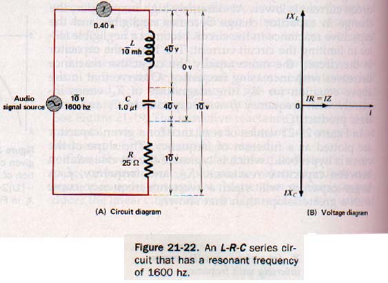
Resonance is the situation where XL = XC. These two vectors cancel at resonance leaving Resistance as the resultant. Here is an L-R-C series circuit:
SUMMARY
The power expended in the load of an a-c circuit is determined by the average of the instantaneous values over the period of one cycle. Instantaneous power is the product of the instantaneous current and the instantaneous voltage. In a resistive load, the average power is the product of the effective values of current and voltage. In either a pure inductive load or a pure capacitive load, the average power is zero.
Power in an a-c circuit is equal to the product of the effective value of the current, the effective value of the voltage, and the cosine of the phase angle. An a-c circuit containing both inductance and resistance produces a current that lags behind the voltage. Such a load presents an impedance to the source. This impedance is the vector sum of the resistance and the inductive reactance in the circuit. The phase angle is the angle at which the current lags the voltage.
Capacitance and resistance in an a-c circuit produce an impedance equal to the vector sum of the capacitive reactance and resistance in the circuit. The phase angle in this case is due to a lagging voltage.
When inductance and capacitance are both present, the phase angle is determined-by the relative magnitudes of the two reactances. Inductive reactance is directly proportional to both frequency and inductance. Capacitive reactance is inversely proportional to both frequency and capacitance.
Series circuits containing inductance, capacitance, and resistance can; be analyzed by the application of Ohm's law for a-c circuits.
At zero frequency the reactance of an inductor is zero, with a linear increase as the frequency increases. The reactance of a capacitor is infinitely large at zero frequency and decreases nonlinearly with increasing frequency.
The resonant frequency of the circuit is the frequency at which the inductive and capacitive reactances of a circuit are equal.
At the resonant frequency the impedance of a series-resonant circuit is at a minimum and is equal to the circuit resistance. The resonant current is the maximum current possible in the series circuit and is in phase with the applied voltage.
If the Q of the circuit is high, the resonant current is very large compared with the average circuit current over a range of frequencies. The current curve is sharply peaked. The selectivity of such a resonant circuit is high.
VOCABULARY
actual power, apparent power, arc tangent capacitance, capacitive reactance, capacitor, effective value (of current or voltage), impedance, impedance diagram, inductance, inductive reactance, inductor, phase angle, phase diagram, phasor, power factor, reactance, resonance resonant frequency, root-mean-square, selectivity, series resonance.
Ah Yaz Indeed!
 Assignment Sheet for this Research Text Only.
 Go to Textbook Assignments for Portfolio:
.................................First Semester
.................................Second Semester